How to Wire a 3-Way Switch (With Diagrams for Every Layout)
Last updated: October 2026 · By Tony T. Johnson
Quick answer: To wire a 3-way switch, connect the common wire to the dark (black) screw. On the first switch, the common is the hot from the panel. On the second switch, it’s the wire to the light. Then connect the two traveler wires (usually red and black in a 3-wire cable) to the two brass screws on both switches, and the bare copper wire to the green ground screw. Travelers can go on either brass screw. The common must go on the dark screw.
A 3-way switch setup lets you control one light from two places, like the top and bottom of a staircase. It uses two 3-way switches joined by two traveler wires. If you understand which wire is the common and which are travelers, every 3-way job makes sense.
⚠️ Safety first: turn off the circuit at the breaker and confirm it’s dead at the switch with a non-contact voltage tester before touching any wire. Many jurisdictions require a permit for new wiring, and some require a licensed electrician. If your home has aluminum branch wiring, cloth-insulated wiring, or no ground wires, stop and call a licensed electrician.
| At a glance | |
|---|---|
| Time | 30–60 minutes to replace a pair. Several hours to run new cable. |
| Difficulty | Moderate |
| Tools | Non-contact voltage tester, multimeter (for continuity), screwdriver, wire stripper, needle-nose pliers, electrical tape |
| Materials | Two 3-way switches, wire nuts or lever connectors. For new runs: 14/3 cable for 15-amp circuits or 12/3 for 20-amp circuits (with ground), plus 14/2 or 12/2. |
How a 3-way switch works
A regular (single-pole) switch has two screws plus ground and simply opens or closes one wire. A 3-way switch has three screws plus ground:
| Terminal | Color (usual) | What it connects |
|---|---|---|
| Common (COM) | Dark / black screw | The incoming hot (switch 1) or the wire going to the light (switch 2) |
| Traveler 1 | Brass / light screw | One of the two wires running between the switches |
| Traveler 2 | Brass / light screw | The other wire between the switches |
| Ground | Green screw | Bare copper or green ground wire |
Inside, a 3-way switch connects the common to either traveler 1 or traveler 2. Flipping either switch changes which traveler carries power. The light turns on when both switches point to the same traveler. That’s why 3-way switches have no ON/OFF printed on the toggle.
Real question from a forum: “What is L1 and COM on a switch?”
On many 3-way and smart switches, COM is the common terminal, and L1/L2 (or “Traveler 1/2”) are the traveler terminals. Smart switches add Line (incoming power), Load (to the light) and Neutral. Always follow the labels on the switch itself.
Before you remove the old switch: label everything
This one step prevents most 3-way mistakes.
- Turn off the breaker and verify with a voltage tester.
- Remove the cover plate and pull the switch out of the box.
- Find the dark screw (sometimes labeled COM) and put a wrap of tape on that wire. That’s the common.
- The wires on the two brass screws are travelers. Mark them “T” (which one goes on which brass screw doesn’t matter).
- Take a photo.
- Repeat at the other switch.
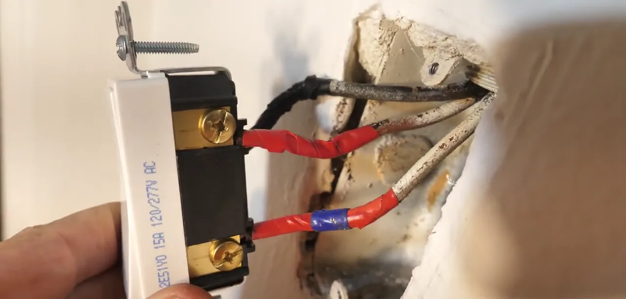
If you’ve already disconnected the wires and lost track, see “How to find the common wire” below.
Wiring diagrams: the 3 most common layouts
Layout 1: Power comes into the first switch, the light is after the second switch
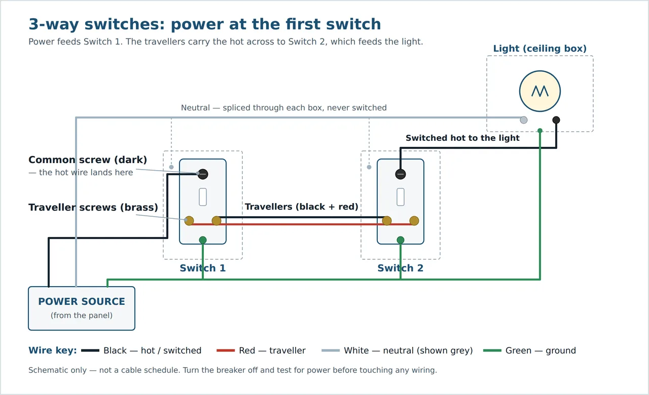
PANEL ──14/2──► [SWITCH 1] ══14/3══ [SWITCH 2] ──14/2──► LIGHT

         hot → COM        black = traveler     COM → black to light

                          red   = traveler

       neutral (white) ── spliced straight through both boxes ──► light
Switch 1 box:
- Incoming black (hot) → COM (dark screw) on switch 1
- 14/3 red and black → the two brass traveler screws
- Incoming white → splice with the 14/3 white (neutral continues to switch 2)
- All grounds spliced together, with a pigtail to the switch’s green screw
Switch 2 box:
- 14/3 red and black → the two brass traveler screws
- Black wire going to the light → COM (dark screw)
- 14/3 white → splice with the white going to the light
- All grounds spliced together, with a pigtail to the green screw
At the light: black → fixture hot (black/brass). White → fixture neutral (white/silver). Ground → fixture ground.
Layout 2: Power comes into the light first (switches on each side)
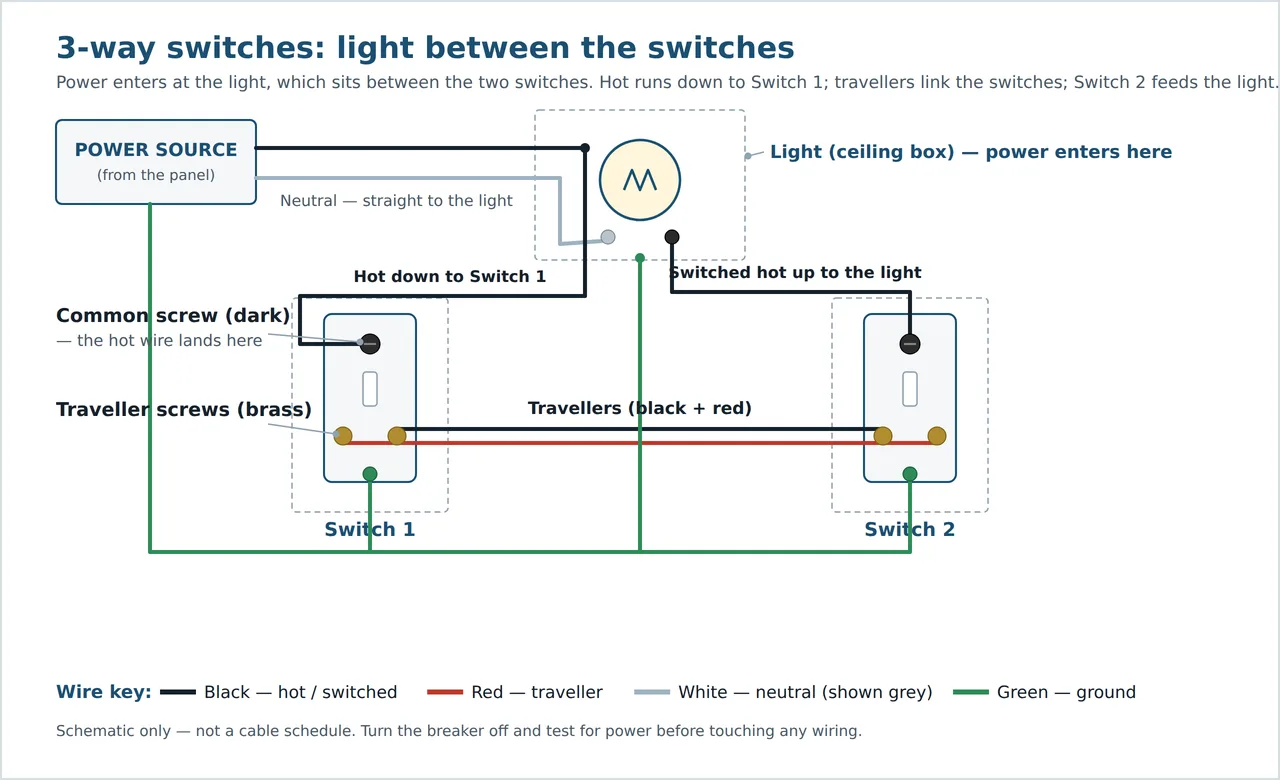
PANEL ──► LIGHT BOX ──14/3──► [SWITCH 1] ══14/3══ [SWITCH 2]
The light sits between the two switches, with a 3-wire cable from the light box to each switch. A typical existing installation is wired like this:
- Light box:
- Panel black (hot) → black wire of the cable to switch 1
- Black wire of the cable from switch 2 → fixture hot
- Panel white (neutral) → fixture neutral
- The two travelers pass through: red to red, and white to white (the whites are used as travelers)
- All grounds together
- Switch 1: black (hot) → COM. Red and white → the brass traveler screws.
- Switch 2: black (to the light) → COM. Red and white → the brass traveler screws.
Wherever a white wire is used as a traveler or hot, it must be re-identified with black or red tape at both ends (NEC 200.7(C)). This older layout leaves no neutral at either switch. For new work, current code generally requires a neutral at switch locations, so new runs need an extra conductor (such as 4-wire cable) or a different layout.
Because the wire colors don’t line up neatly in this layout, follow the diagram that came with your switch, or have an electrician confirm it.
Layout 3: Power at the light, both switches beyond it (switch loops)
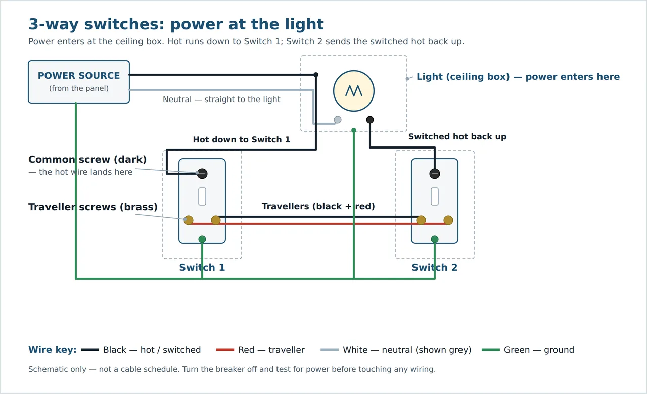
Older homes often have a light fed first, with 3-wire cable running to one switch and on to the other. The white wire may be used as a traveler or a switched hot rather than as a neutral. That makes these the setups most likely to confuse DIYers.
Current code (NEC 404.2(C), since the 2011 edition) generally requires a neutral at most switch locations. So new work usually runs cable with an extra conductor, or uses a different layout. If you’re adding a smart switch, a neutral at the box is usually required.
How to replace an existing 3-way switch (step by step)
- Power off at the breaker. Verify with a tester at both switch boxes.
- Label the common (dark screw) at the old switch with tape, and photograph the connections.
- Disconnect the wires and remove the old switch.
- Connect the common wire to the dark (COM) screw on the new switch.
- Connect the two travelers to the brass screws (either order).
- Connect the ground to the green screw.
- Use the side screws. Wrap the wire clockwise under the screw head and tighten firmly. Avoid push-in “backstab” holes, which many electricians consider less reliable.
- Fold the wires neatly into the box, mount the switch, and install the cover plate.
- Restore power and test every combination: up/up, up/down, down/up, down/down. The light should change state each time either switch is flipped.
How to find the common wire (if you lost track)
Method 1: Look at the old switch. The common is on the dark-colored screw, sometimes labeled COM.
Method 2: Continuity test (power OFF, switch removed):
- Set a multimeter to continuity.
- Put one probe on a screw. Flip the toggle back and forth while touching the other probe to each of the other two screws.
- The common is the screw that has continuity with one traveler in the up position and the other traveler in the down position.
Method 3: Voltage test at the wires (only if you’re experienced, power ON, careful): at the switch 1 box, the incoming hot from the panel reads 120 V to ground no matter how the other switch is set. That wire is switch 1’s common. If you aren’t comfortable testing live wires, hire an electrician.
Three way switch wiring troubleshooting
| Symptom | Most likely cause | Fix |
|---|---|---|
| Light works only when the other switch is in one position | Common and a traveler swapped on one switch | Find the true common (see above) and move it to the dark screw |
| Each switch works alone, but not together | A traveler is connected to the wrong switch’s common, or the travelers are crossed with a different circuit | Re-trace the travelers. Both brass screws on each switch must connect to the same two traveler wires. |
| Light never turns on | Loose connection, a bad switch, or a tripped breaker or GFCI | Check connections and test the switches for continuity |
| Turns off but won’t turn on (or the reverse) | Common miswired, or a failed switch | Confirm the common at both ends. Replace a faulty switch. |
| Breaker trips when flipping the switch | A hot touching the ground or neutral (a short) | Turn off power immediately, inspect for nicked insulation or misplaced wires |
| Light flickers | Loose connection, or an LED and dimmer mismatch | Tighten the terminals. Use a dimmer rated for LEDs. See flickering lights. |
Real question from a forum: “I replaced both kitchen 3-way switches. Each works on its own, but not together.”
That pattern almost always means a common got moved to a brass traveler screw on one or both switches. Turn off the power, identify the common at each box (the wire that was on the dark screw, or by continuity testing), put it back on the dark screw, and the pair will work again.
How to wire a 3-way dimmer or smart switch
- 3-way dimmers: usually only one of the two switches is a dimmer, and the other is a standard 3-way switch. Check the dimmer’s instructions, and use an LED-compatible dimmer if you have LED bulbs.
- Smart 3-way switches: most systems use one smart main switch plus a companion (add-on) switch at the other location. Wiring differs by brand. Many reuse one traveler as a communication wire and need a neutral at the main switch. Follow the brand’s diagram exactly, and identify Line (incoming power) and Load (to the light) with a tester first.
Adding a third location: the 4-way switch
To control a light from three or more places, put a 4-way switch between the two 3-way switches. The 4-way has four traveler screws (two pairs: in and out) and no common. The travelers from switch 1 connect to one pair, and the travelers to switch 2 connect to the other pair.
Converting a single-pole switch to a 3-way
You need a 3-wire cable (14/3 or 12/3 with ground, matching the circuit’s wire size) between the two switch locations. That usually means fishing new cable through walls, and in many places a permit. If there’s no 3-wire cable between the locations, a smart switch with a wireless remote companion is a code-friendly alternative that needs no new travelers.
When to call a licensed electrician
- There’s no ground wire, or the wiring is aluminum or knob-and-tube
- You need to run new cable or add a switch location
- The box is overcrowded (box fill limits under NEC 314.16)
- You can’t identify which wire is which after testing
- Anything scorched, melted or smelling of burning
FAQs
What wire goes to the black screw on a 3-way switch?
The common wire. On the switch nearest the power source, that’s the incoming hot from the panel. On the other switch, it’s the wire running to the light fixture.
Does it matter which traveler goes on which brass screw?
No. The two traveler wires can go on either brass screw on each switch. Only the common wire has a specific terminal: the dark (black) screw.
What is the red wire on a 3-way switch?
In a 3-wire cable (black, red, white and bare), the red and black wires usually serve as the two travelers between the switches. In some layouts, red is a switched hot to the light.
Why does my 3-way switch only work when the other switch is up?
The common wire and a traveler have been swapped on one of the switches. Turn off the power, find the true common on each switch, and connect it to the dark screw.
Can I use one 3-way switch as a regular switch?
Yes. A 3-way switch can replace a single-pole switch if you connect the two wires to the common and one traveler. The toggle won’t have consistent “up is on” markings. This doesn’t work the other way around: a single-pole switch can’t replace a 3-way in a two-switch circuit.
What gauge wire do I need for a 3-way switch?
Match the circuit. Use 14-gauge wire (14/2 and 14/3 cable) on 15-amp circuits and 12-gauge (12/2 and 12/3) on 20-amp circuits. Check the breaker before buying.
Do 3-way switches need a neutral wire?
Standard mechanical 3-way switches don’t connect to the neutral. Current code generally requires a neutral to be available in most switch boxes, and most smart switches need one to work.
How do I wire a 3-way switch with two lights?
Wire the 3-way switches as usual, then connect the second fixture in parallel with the first at the light: switched hot to switched hot, neutral to neutral, ground to ground. Both lights will turn on and off together.
About the author: Tony T. Johnson, founder and lead editor of HomeRevampDaily.